

A DXF handoff usually fails in a boring way. Engineering exports a file, the shop opens it, nothing looks obviously wrong, and the first clue appears when the machine cuts the wrong contour, drops a hole center, or scales a profile incorrectly. By that point, you've already paid for setup time, machine time, material, and schedule disruption.
That's why I don't treat the DXF file format as an administrative detail. In manufacturing, it's a communication tool. If the file carries the right geometry, structure, units, and context, production moves. If it doesn't, teams start interpreting, redrawing, and asking avoidable questions. That's where margin disappears.
I've seen leaders focus heavily on design quality and machine capability while underestimating the handoff layer between them. That gap creates scrap, rework, supplier friction, and delayed shipments. Strong operations teams close it with process discipline, file standards, and repeatable review steps, much like the broader principles behind manufacturing process improvement.
Table of Contents
- Introduction The Hidden Costs of a Bad Handoff
- What Is a DXF File and Why Was It Created
- Inside a DXF File A Blueprint's Anatomy
- DXF vs DWG Choosing the Right Format for Exchange
- DXF in Action The Backbone of CNC and Precision Manufacturing
- Mastering DXF Exchange Best Practices and Workflows
- Troubleshooting Common DXF Problems and Looking Ahead
Introduction The Hidden Costs of a Bad Handoff
A design can be perfect inside CAD and still fail on the floor.
A common example is a flat pattern that looks clean in the engineering system, then arrives at a laser or waterjet with open contours, duplicated entities, or text sitting on the same layer as cut geometry. The operator doesn't always catch it immediately. The CAM software imports something that appears usable, a program gets posted, and the first article exposes the problem.
The expensive part isn't only the bad part. It's the chain reaction. Purchasing asks whether the material order needs to be revised. Production control reshuffles the queue. Quality has to document a nonconformance. Engineering gets pulled back into a file they thought was complete. Supplier confidence drops if the problem crosses company boundaries.
Practical rule: If a shop has to interpret your DXF, your handoff process is incomplete.
New engineering leads often inherit this issue because everyone around them assumes DXF is simple. It isn't. It's familiar, widely supported, and effective when used correctly, but it still requires discipline. A clean handoff means more than pressing Export. It means deciding what information the receiving software and machine need, then checking whether that information survived translation.
That's the operational lens that matters. The DXF file format isn't just about interoperability between software packages. It's about preserving design intent well enough that the finished part matches the commercial, quality, and scheduling expectations attached to it.
What Is a DXF File and Why Was It Created
DXF stands for Drawing Exchange Format. Autodesk introduced it in December 1982 as part of AutoCAD 1.0 so drawings could move between different computing platforms and CAD systems while still representing AutoCAD's native DWG data accurately, according to the AutoCAD DXF history summary.
That origin tells you almost everything important about the format. DXF wasn't created to be elegant. It was created to make exchange possible.

The business problem DXF solved
In the early CAD world, companies had a practical problem. A drawing created in one environment often couldn't move cleanly into another. That blocked collaboration between design teams, suppliers, customers, and production groups using different systems.
DXF became a workable answer because it represented drawing information in a structured, tagged format rather than locking it inside one proprietary workflow. The format describes drawing data through numeric group codes paired with values. That's a technical detail, but the business implication is more important: software developers could read it, write it, and build support for it.
As a result, DXF became one of the earliest widely adopted CAD exchange formats. It earned trust because it solved a real operational problem that manufacturers still have today. Different teams still use different tools. Different suppliers still run different software. Interoperability still matters.
Why that origin still matters
The same design choice that made DXF useful also explains its limits. It's excellent when you need a common language. It's less impressive when you expect it to carry every nuance of a native model.
That's why DXF remains relevant in fabrication, drafting, CNC, and supplier communication. It speaks broadly enough to move geometry and drawing elements across systems. It also tends to flatten richer design intelligence when the source model contains more than the receiving workflow can interpret.
A good DXF is rarely the richest file in the process. It's the clearest one.
For manufacturing leaders, that distinction matters. You don't choose DXF because it preserves everything. You choose it because it preserves enough of the right things to let another system act on the design reliably.
Inside a DXF File A Blueprint's Anatomy
A DXF file isn't a digital picture of a drawing. It's closer to a structured instruction sheet.
Independent format references describe DXF as a CAD interchange format built around group codes and value pairs, organized into sections such as HEADER, TABLES, BLOCKS, ENTITIES, and OBJECTS in a detailed DXF format reference. That structure is why DXF can preserve layers, blocks, and annotations, not just raw lines.
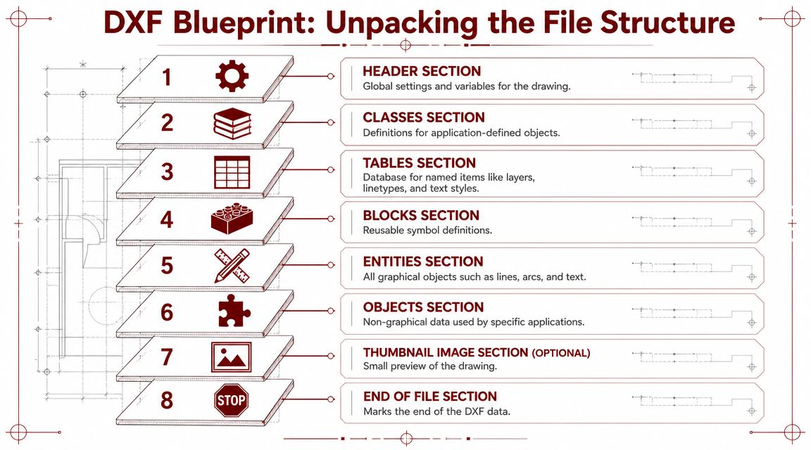
Think of DXF as instructions not a picture
If you think about a paper blueprint, the title block, symbols, notes, dimensions, and geometry all play different roles. DXF works similarly. Its sections separate different kinds of information so software can parse them.
Here's the practical version:
- HEADER holds drawing-level settings. Software references this section for core variables that affect interpretation.
- TABLES stores named definitions such as layers, linetypes, and text styles.
- BLOCKS defines reusable objects or symbols.
- ENTITIES contains the geometry most manufacturing teams care about most directly, such as lines, arcs, circles, text, and related objects.
- OBJECTS carries non-graphical data used by some applications.
When a shop says, “The DXF opened, but something is off,” the problem often sits in one of those layers of structure. Maybe the geometry exists, but the layer organization doesn't. Maybe the block definition came through, but the target system handled it poorly. Maybe the entities imported, but annotation cluttered the toolpath view.
ASCII versus binary in practical terms
The ASCII DXF variant typically encountered is the human-readable form and the most common one. That broad compatibility is one reason the format has lasted.
Autodesk added binary DXF in 1988, and Scan2CAD reports that binary DXF made files 5× faster to read and write while reducing file size by 25% in its history of the DXF format. That sounds attractive, and in some workflows it is.
But in practice, compatibility usually wins over elegance. ASCII DXF is verbose, larger, and heavier to parse than compressed or binary alternatives. Even so, it remains the safer exchange choice when you don't control every downstream system.
Use the variant your receiving process can handle consistently, not the variant that looks best on paper.
That's the recurring DXF lesson. The best file is the one that opens correctly in the other person's software, preserves the intended entities, and doesn't create interpretation work.
DXF vs DWG Choosing the Right Format for Exchange
Most engineering organizations don't need a philosophical answer to DXF versus DWG. They need a policy.
My view is straightforward. Use the native format for internal design work when you want to preserve the richest editable information. Use DXF when the file has to leave that native environment and land safely in another toolchain.
Where each format works best
DWG is generally the better working file inside an Autodesk-centric environment. DXF is generally the better handoff file when compatibility matters more than richness.
That doesn't make DXF superior overall. It makes DXF superior for a specific job.
| Attribute | DXF (Drawing Exchange Format) | DWG (DraWinG) |
|---|---|---|
| Primary role | Exchange and interoperability | Native design and editing workflow |
| Best use case | Sending drawings to vendors, CAM systems, customers, or mixed-software teams | Internal collaboration where the full native model context matters |
| Readability | Often human-readable in ASCII form | Native format, not aimed at human readability |
| Compatibility | Broadly supported across many CAD and CAM workflows | Best inside ecosystems built around DWG support |
| File efficiency | Can be verbose, especially in ASCII form | Typically better suited to native editing and storage |
| Data richness in practice | Strong for exchange, especially 2D drawing data | Better for preserving native editing context |
A few operating rules help:
- Use DWG internally when your team is still designing, revising, detailing, or archiving within software that handles it natively.
- Use DXF externally when a supplier, machine programmer, or customer needs dependable access to geometry.
- Don't assume equivalent results just because one can be exported from the other.
- Define approved deliverables by workflow. A laser shop may want one kind of DXF package. A customer review set may need something different.
The mistake I see most often is not choosing the wrong format. It's choosing without naming the purpose. If the purpose is editing in the native system, DXF may strip too much context. If the purpose is safe exchange, DWG may create avoidable compatibility friction.
DXF in Action The Backbone of CNC and Precision Manufacturing
DXF earns its keep on the shop floor because machines don't need a philosophy of design. They need usable geometry.

For manufacturing and CAM workflows, the practical value of DXF comes from its ability to represent 2D geometry with high fidelity, while still functioning as a least common denominator exchange format used mainly for 2D wireframes, contours, and drafting data rather than full solid-model intelligence, according to the Library of Congress format guidance.
Why CAM systems like DXF
CNC, laser cutting, waterjet, routing, and sheet-metal workflows often begin with a profile, contour set, or flat pattern. DXF handles that handoff well because the receiving CAM software can map entities like lines, arcs, and curves into toolpath logic.
That's the reason DXF has remained so practical. It tells the downstream software where geometry exists with enough fidelity to let a programmer generate machine motion. It's direct, widely recognized, and familiar across many fabrication environments.
In mixed operations, that matters more than theoretical perfection. A supplier network rarely runs one software stack. A plant with multiple machine types rarely has one ideal native format for everything. DXF works because it provides a common floor.
If your team manages different machining methods, it helps to understand where geometry transfer intersects with process choice, especially in parts that move between contour-based and turned features. A broader review of CNC turning versus Swiss machining gives useful context for those handoff decisions.
What the machine never sees
The danger starts when teams assume a machine receives the whole design story. It doesn't.
DXF is strong at conveying cut paths and drafting geometry. It is weak as a complete carrier of parametric history, feature intent, and richer model semantics. That's why an apparently correct file can still generate confusion on the floor. The contour survives. The reasoning behind the contour may not.
When production depends on DXF, engineering has to make intent visible in other ways.
That usually means layer conventions, clean notes outside the cut geometry, revision control, and a separate release package that clarifies what's critical.
For teams that want to see this concept from the machine side, this video gives a useful visual of the translation from file to fabrication:
An effective operation doesn't ask DXF to do work it was never meant to do. It uses DXF for what it does well, then surrounds it with controls that protect the rest.
Mastering DXF Exchange Best Practices and Workflows
Bad DXF files rarely come from bad intentions. They come from lazy defaults.
A key challenge is that DXF does not carry the full parametric feature history, and gaps around blocks and layouts can cause a seemingly simple export to lose design intent and create rework, as discussed in this explanation of DXF handoff limitations. That means export quality is not optional. It's part of manufacturing quality.
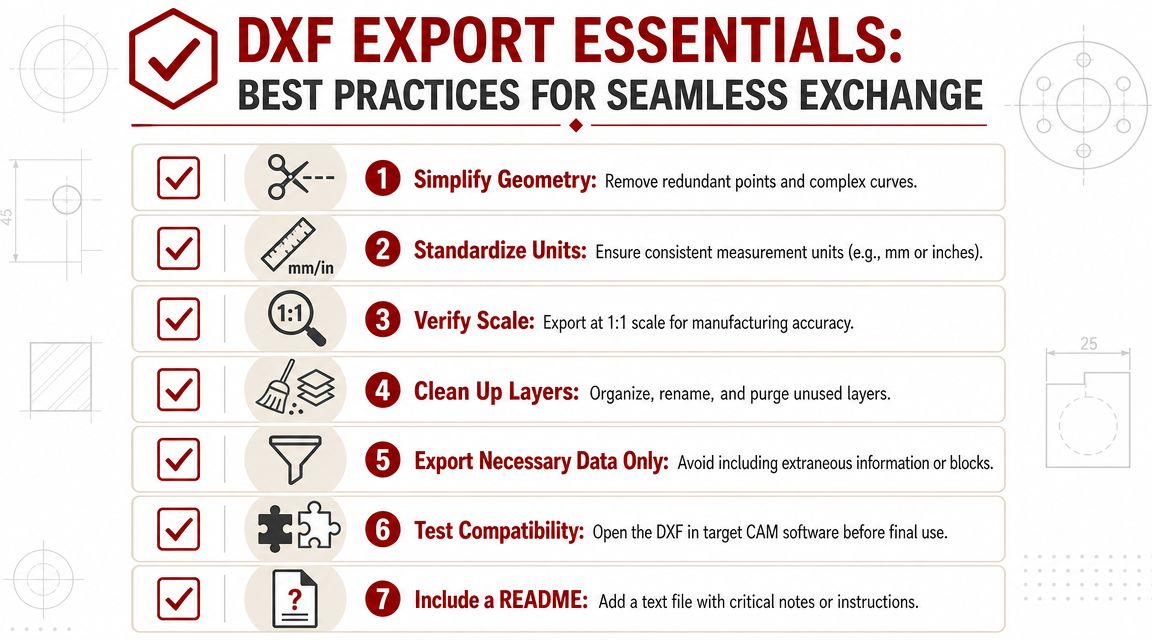
The export checklist that prevents rework
A disciplined DXF workflow usually includes the following checks before release:
- Simplify the geometry. Remove duplicate entities, stray construction lines, and unnecessary detail that CAM doesn't need.
- Control units explicitly. Never assume the receiver will infer inch versus millimeter correctly.
- Export at true scale. Manufacturing geometry should arrive at 1:1 unless a very specific downstream requirement says otherwise.
- Purge clutter. Unused layers, title block content, dimensions, and notes can confuse import routines or operators.
- Handle blocks carefully. If the receiving software struggles with blocks, convert them into simpler geometry before release.
- Check contours. Closed profiles should be genuinely closed, not visually closed.
- Open the file in the target environment if possible. The export is only done when the receiving software reads it correctly.
- Send a short companion note. If there's a critical surface, no-cut region, bend assumption, or revision caveat, say it plainly.
A release-ready DXF should answer the operator's first questions before the phone rings.
Build the handoff into your operating system
The strongest companies don't leave DXF quality to individual judgment. They build it into process.
That usually means a simple SOP for every outbound manufacturing file: approved export settings, naming rules, revision control, unit declaration, and a final verification step. In mature operations, that checklist belongs inside the broader digital production system, not in somebody's memory. In such scenarios, a strong view of manufacturing execution systems and production control becomes useful.
A practical SOP often defines three things:
What gets exported
Only the geometry needed for manufacturing, plus any clearly separated support data.Who verifies it
Not just the designer. Often a programmer, manufacturing engineer, or release reviewer should validate the handoff.What must accompany it
Revision identifier, units, process notes, and any constraints the file itself cannot carry cleanly.
This is one of those small disciplines that has a direct operating payoff. Clean handoffs reduce clarification loops, programming delays, and part-level surprises.
Troubleshooting Common DXF Problems and Looking Ahead
Most DXF problems fall into a short list.
Common problems and likely causes
The part imports at the wrong size.
The usual cause is unit mismatch or scaling applied during export or import.Contours won't toolpath.
Open geometry, tiny gaps, overlapping entities, or fragmented splines usually sit behind this.Text, dimensions, or title block objects interfere with programming.
Too much drafting information came through with the manufacturing geometry.Blocks or layouts don't behave as expected.
The source system exported objects the receiving system interprets differently.Curves look faceted or odd.
Entity conversion changed how the receiving software represents splines or arcs.
The fix is rarely heroic. Clean the file, simplify entities, confirm units, reopen it in the target software, and treat the imported result as a first article for data, not just for the part.
Where DXF still fits
DXF remains valuable because compatibility still matters. But newer workflows are changing the standard for what “good exchange” means. In browser-based CAD and AI-assisted design, DXF's age is both a strength and a constraint because broad support comes with larger file sizes and limited semantic data, as noted in Adobe's overview of DXF in modern workflows.
That has a management implication. Keep DXF in the toolkit, especially for fabrication and cross-system exchange, but don't force it into jobs that need richer model intelligence or tighter automation.
There's also a governance lesson here. When a bad file handoff creates a safety or quality event, teams need disciplined reporting, not hallway conversation. A structured system to improve safety with better incident reports can help organizations capture the root cause when digital handoff errors affect operations.
DXF isn't going away soon. It's too useful, too familiar, and too embedded in real production. But the companies that use it best are the ones that understand both sides of the truth. It's dependable for the right handoff, and incomplete if you expect it to carry the whole engineering story.
If you're building or scaling a manufacturing organization, the key advantage comes from tightening the handoff between engineering, operations, and the supply base. Hasit Vibhakar shares practical leadership insight drawn from decades in aerospace, advanced manufacturing, and industrial growth.



Leave a Reply